With the skis and elevons complete I can get on with the rest of the model.
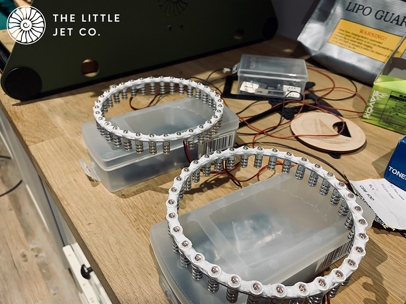
I’m not a huge fan of after burner rings as they don’t look that great in photos and for my taste aren’t very realistic when operating, they just add weight for not a lot of benefit but its all personal preference. I did try and convince the clients to go without but their argument was that they are hoping for film and photos during those golden hours the rings may illuminate the spray during takeoff so wanted to give them a go. I can always remove the rings and wiring at a later date if they don’t work out.
4910B3BA-26FB-410B-B9F2-DE05AB8B5460 by
Alex Jones, on Flickr
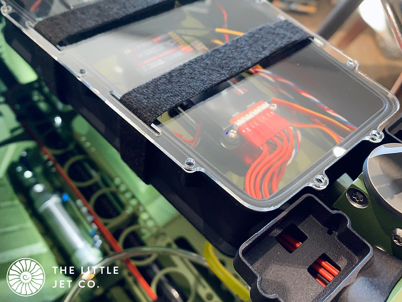
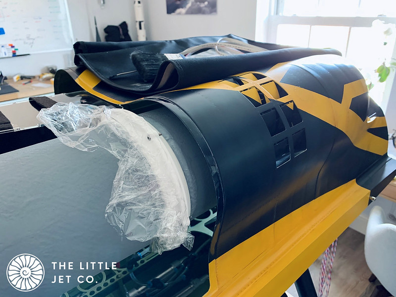
The first job was to try and make the ring splash proof, and disguise its presence which was just a matter of masking each light and spraying black.
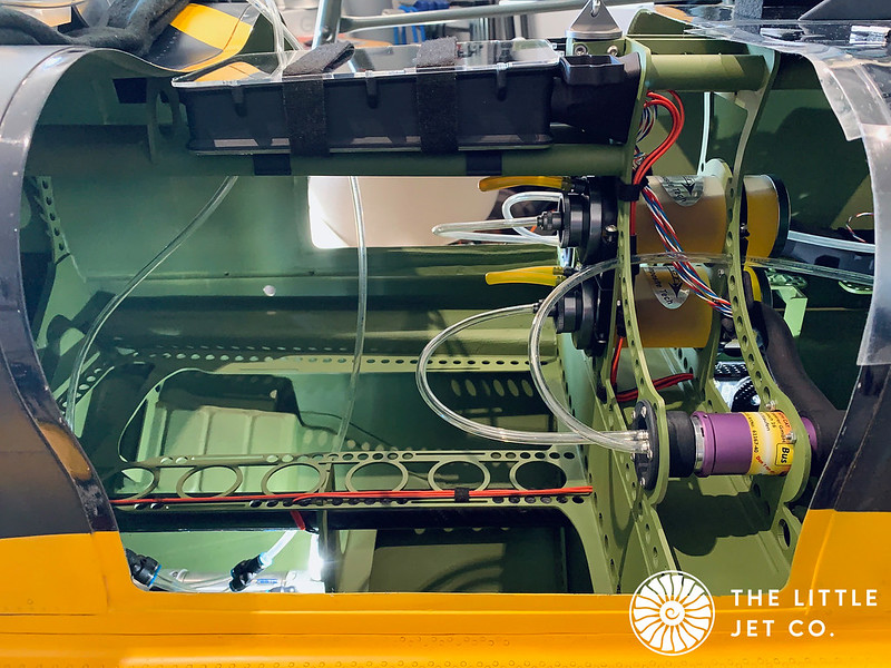
The A/B lights are installed on a carbon ring that sits inside the main duct which allows a through flow of water. I’ve then designed a static part mimicking the look of the petals on the real engine that slots over this, you cant quite see the lights but should get the reflections off the exhaust shroud at least that’s the plan.
E88C3727-8172-4912-B9F4-76BA7EE24FF7 by
Alex Jones, on Flickr
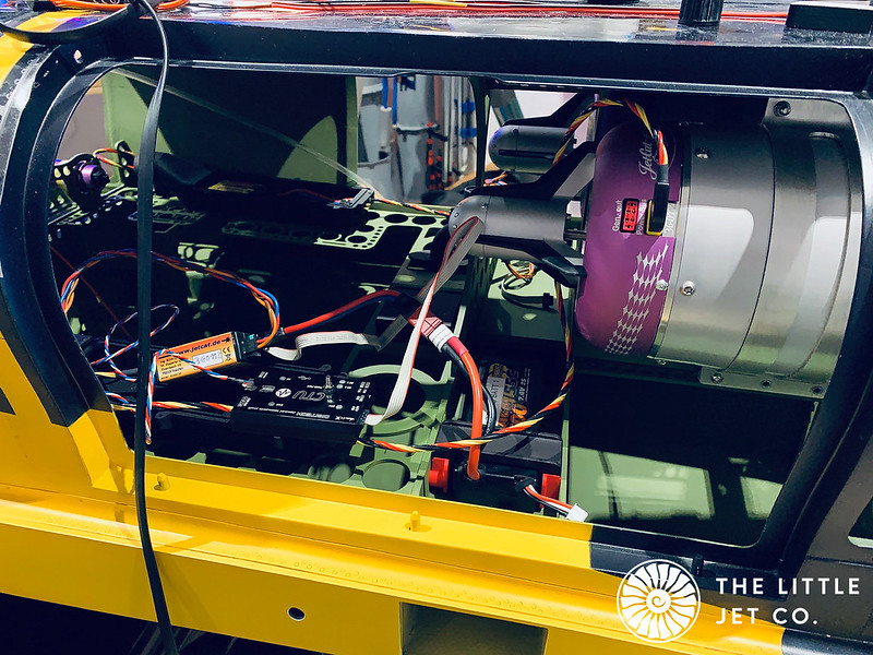
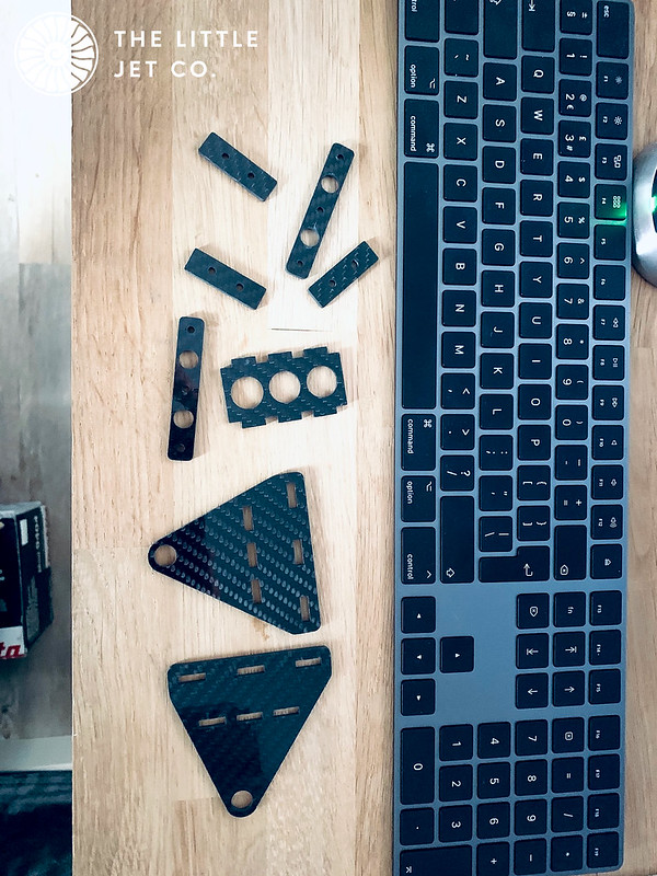
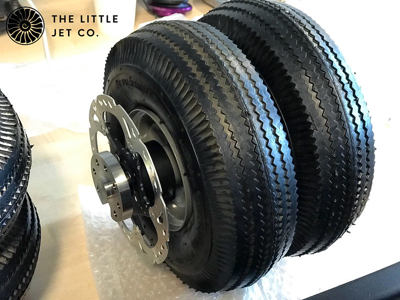
The carbon ring is also used to support the thrust pipe which is mounted inside the main duct using the bell mouth. This duct has a seal which compresses onto the aft turbine bulkhead when bolted allowing water to flow through the intake system. We expect sudden deceleration of the model when the skis submerge from the planed state so expect the following wave to enter aft the aft sections of the intakes. The full-size added considerable amounts of power during this phase to blast the water back out.
CB384615-E2ED-4F0B-820E-9598CE7AD960 by
Alex Jones, on Flickr
669E03D7-0185-4349-A1B1-88EE0D620E1F by
Alex Jones, on Flickr
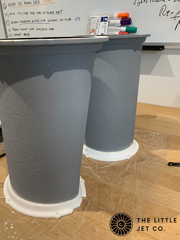
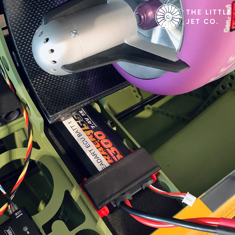
The main duct extends exactly 2mm aft of the last fuselage bulkhead to allow the addition of an o-ring which compresses into a recess in the exhaust shroud when this is bolted up, hopefully providing an effective seal.
3207BD95-4C0F-4168-8E45-0BA96A3EBDBB by
Alex Jones, on Flickr
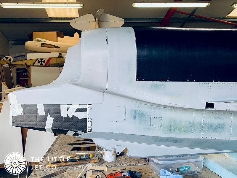
The problem with a hand built pattern which is then digitised and an internal structure designed in CAD is that you end up with a few compromises. Ideally I would have liked the diameter of the main duct to exactly match the diameter of the shroud but this wasn’t the case due to the large radius applied to the duct for moulding and its not exactly circular. The benefit is that it does create a small ridge to block water moving into the intake ducts caused by general surface conditions when the model is just floating waiting for use. It does however catch the light and draw the eye away from the scale parts of the rear end.
E73CAE32-D2FD-4F84-BE8B-785F6745156C by
Alex Jones, on Flickr
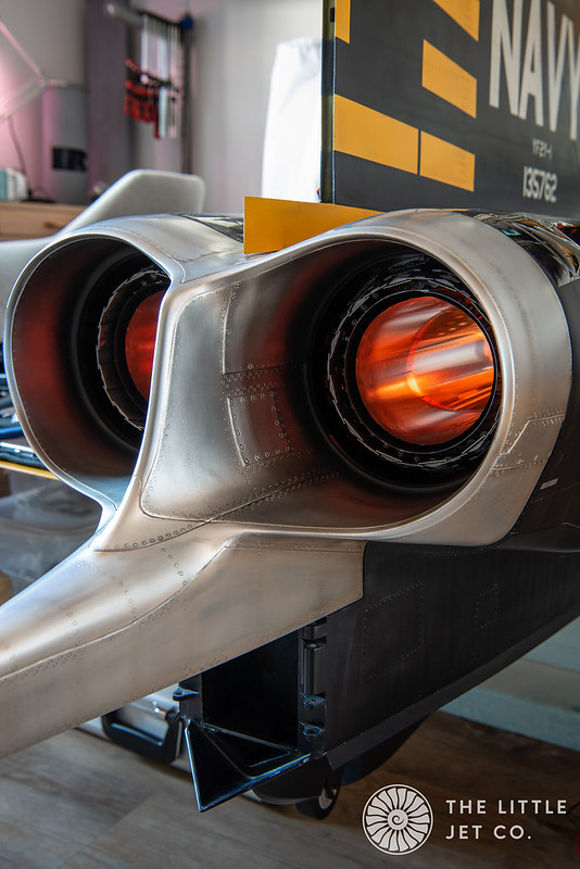
Weathering applied to the shroud and inside edges of the thrust pipe help pull the eye to the static petals. Hopefully this creates a more realistic looking exhaust section.
D443A24B-1290-4590-866A-EC96ED1BD284 by
Alex Jones, on Flickr
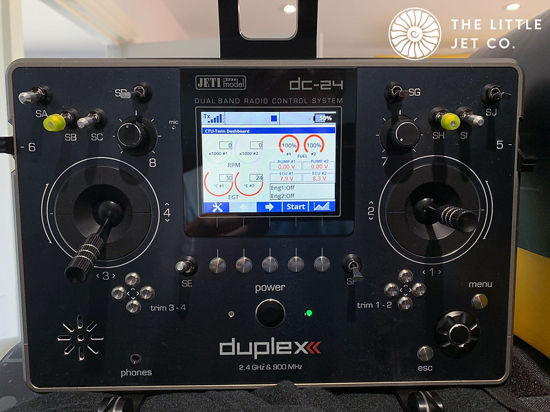
The lighting is courtesy of my sons Philips Hue gaming lights… I was just playing around with effects wondering if a better way A/B lighting would be to get light up the inside of the thrust pipe somehow… anyway, that’s as far as my thoughts went for the time being, perhaps on another model.
 2ADBDE86-5AC5-438A-AF80-9F42D0618494-2 by Alex Jones, on Flickr
 C8E443E8-328F-4C2B-80D9-B2B7CC3C8BFA-2 by Alex Jones, on Flickr
 936BC4C8-6F9D-4952-AD55-F011F3E55A02-3 by Alex Jones, on Flickr
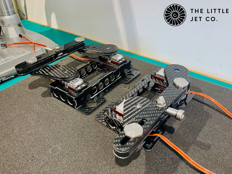


")