The Model (Phase 4)

#1
Onto the actual build...

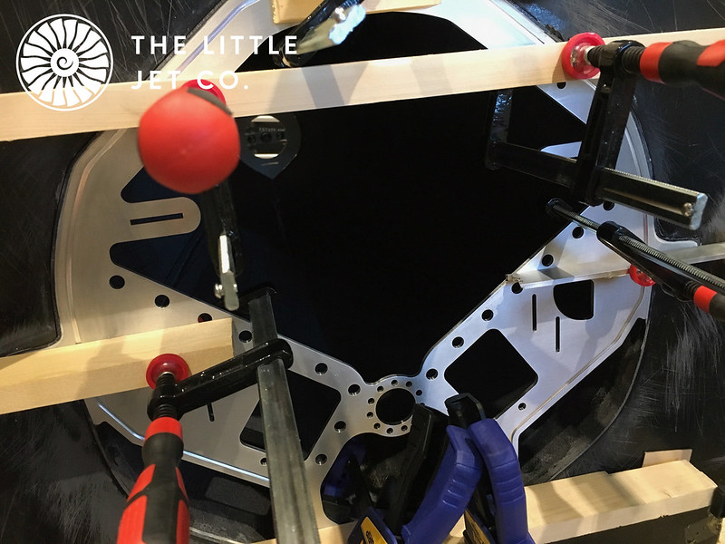
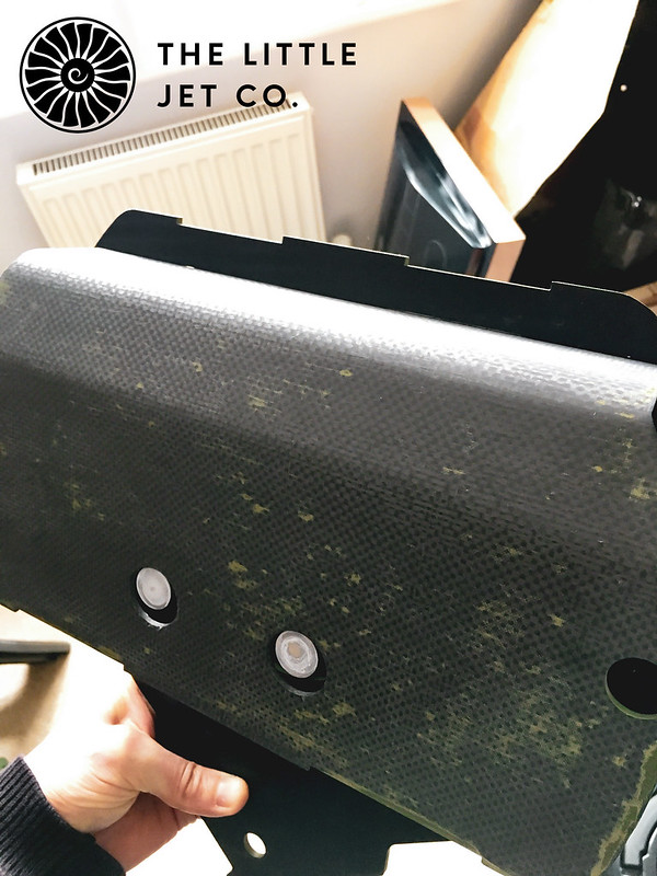
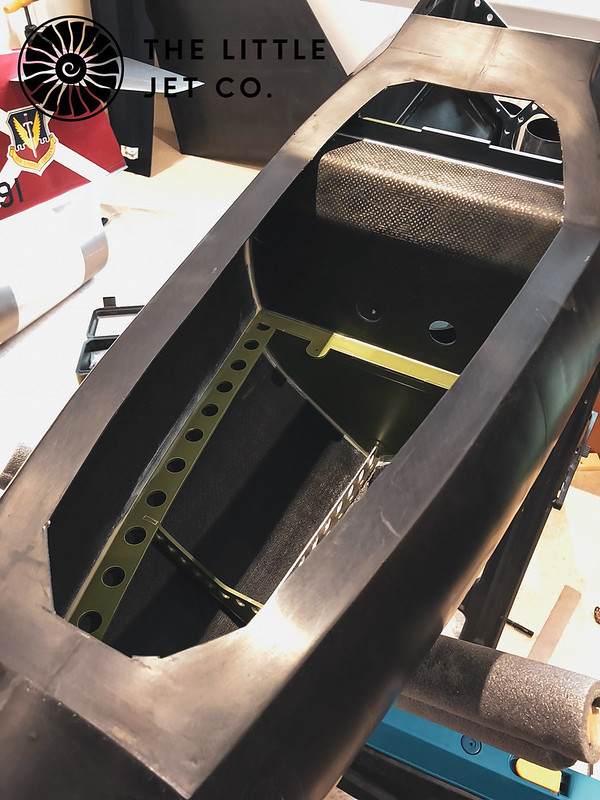
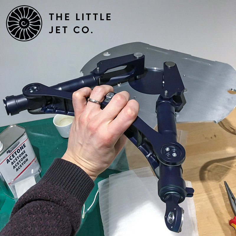
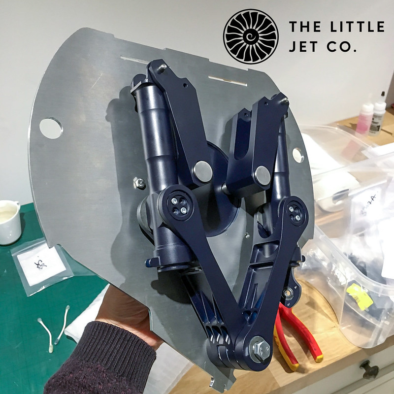
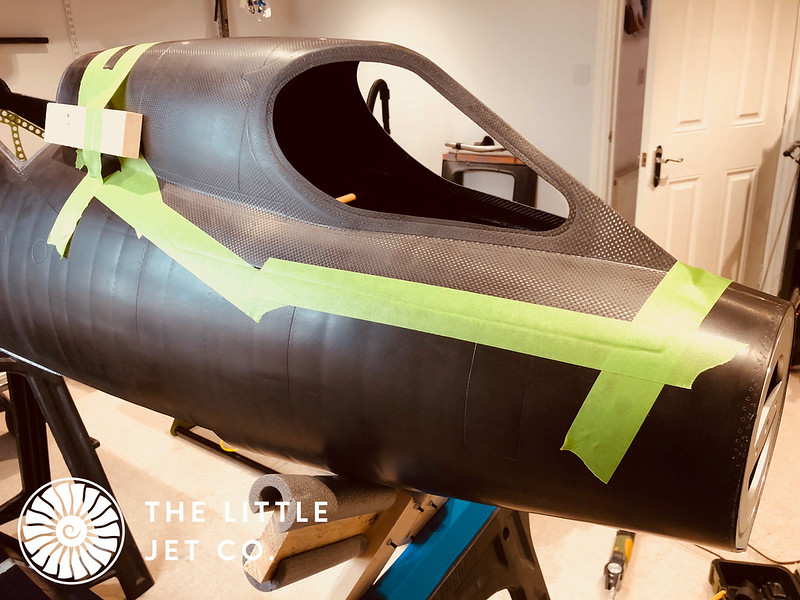
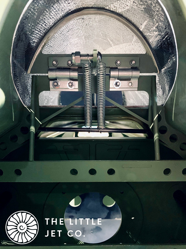
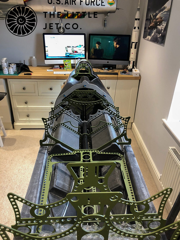
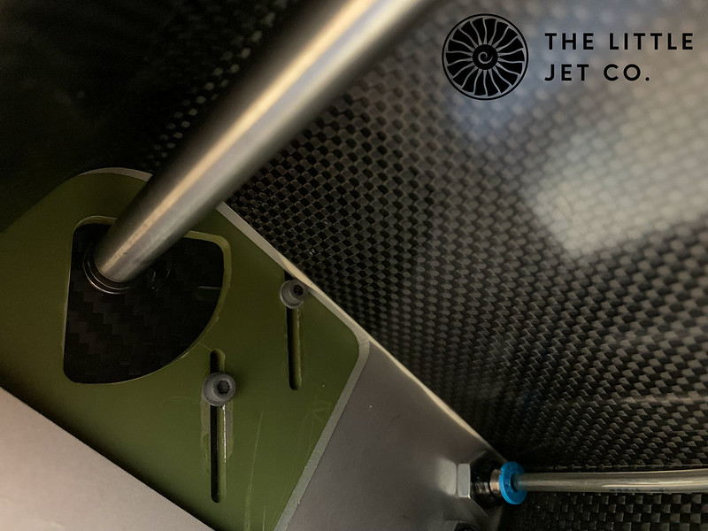
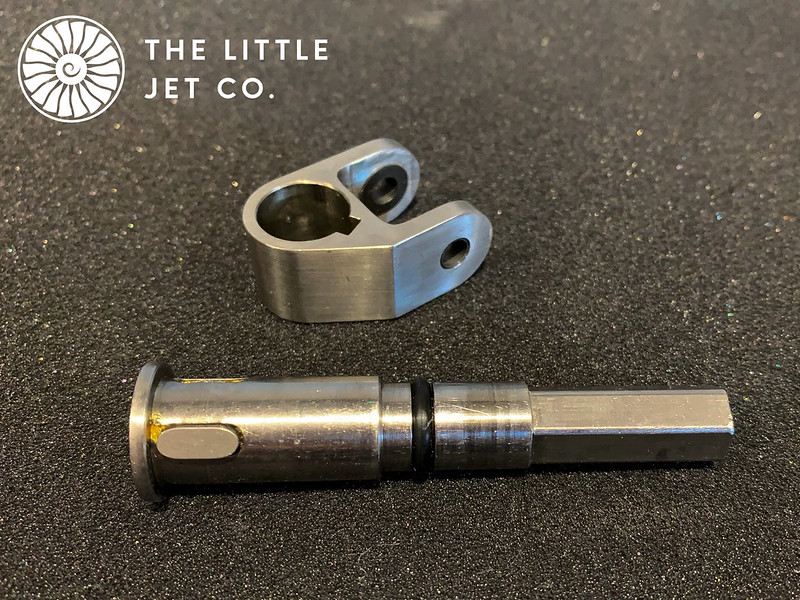
The first task was to cut the apertures for the cockpit and ski wells and install the two main formers that join the rear half of the fuselage to the front section. We have a glass pre-preg fuselage structure with Nomex core and monolithic carbon pre-preg ski wells. The fuselage structure is incredibly strong... I'll demonstrate this by hitting some of the off-cuts with a hammer, it barely makes a scratch! I'll upload the video in the next few days.

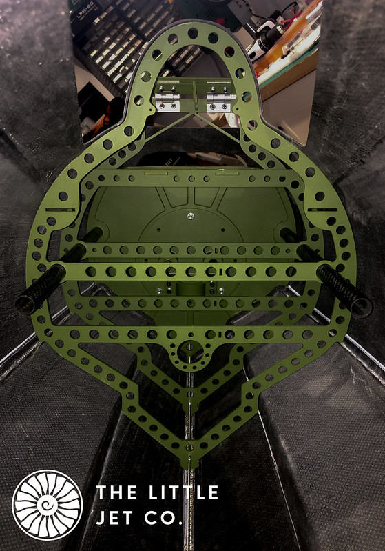
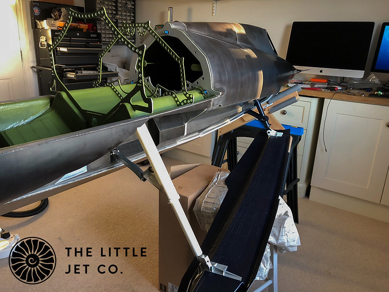
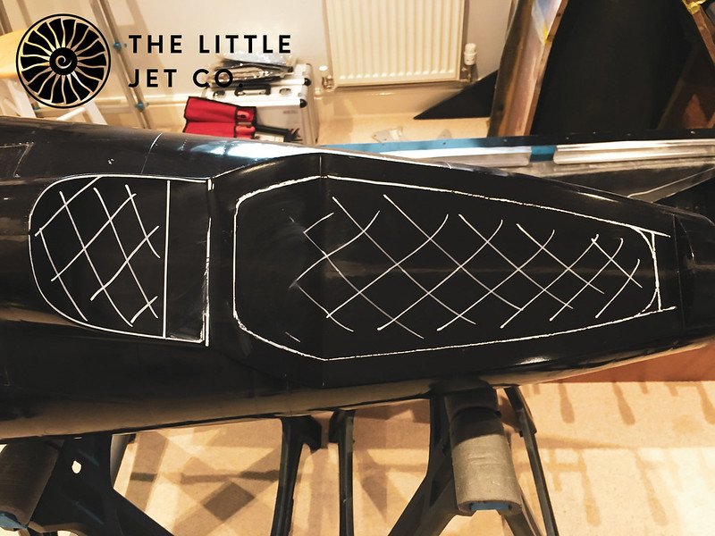
To mark out the apertures I dry fitted all the internal formers and marked the position of the ski well on the inside. I then marked it out again moving inside by 20mm and at each angle change I drilled a hole. Finally joining the dots on the outside and making the cut. Once the ski wells are bonded in I'll cut back the overhang and seal the cut.

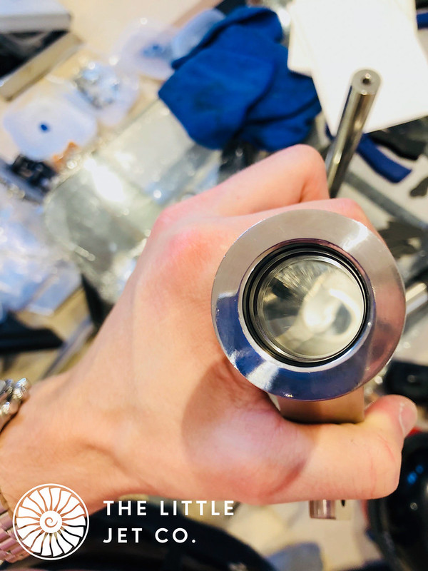
Photos are just from my a phone so apologies for the quality in places.

IMG_2086
by Alex Jones, on Flickr

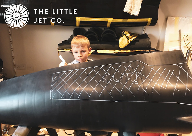
The school holidays is always a challenge... what could possibly go wrong? :)

Screenshot 2018-12-12 at 21.10.27
by Alex Jones, on Flickr

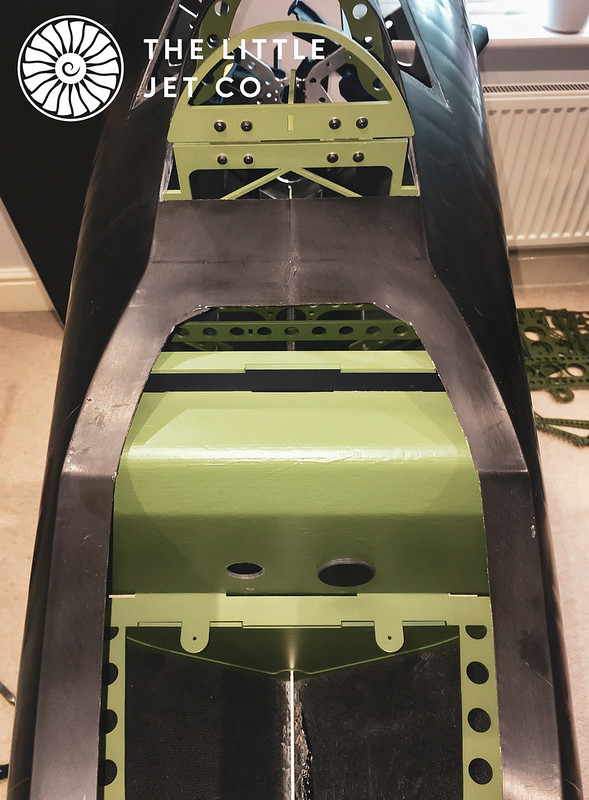
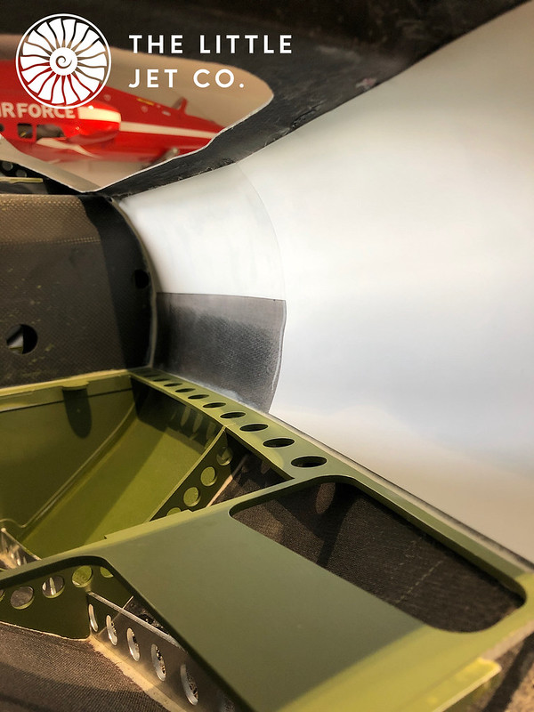
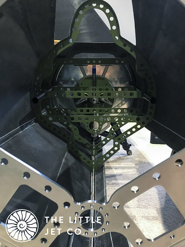
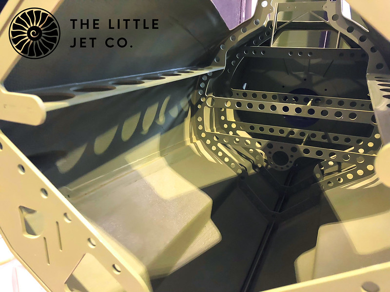
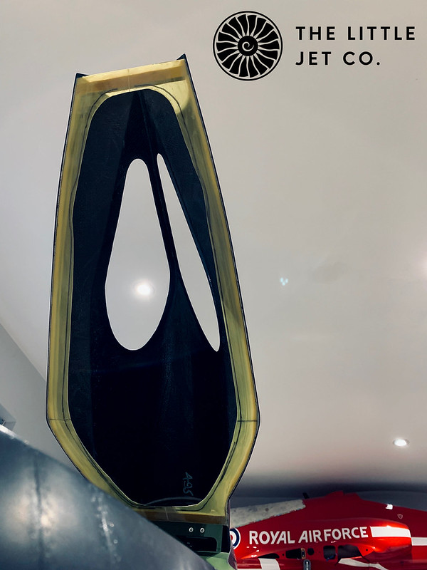
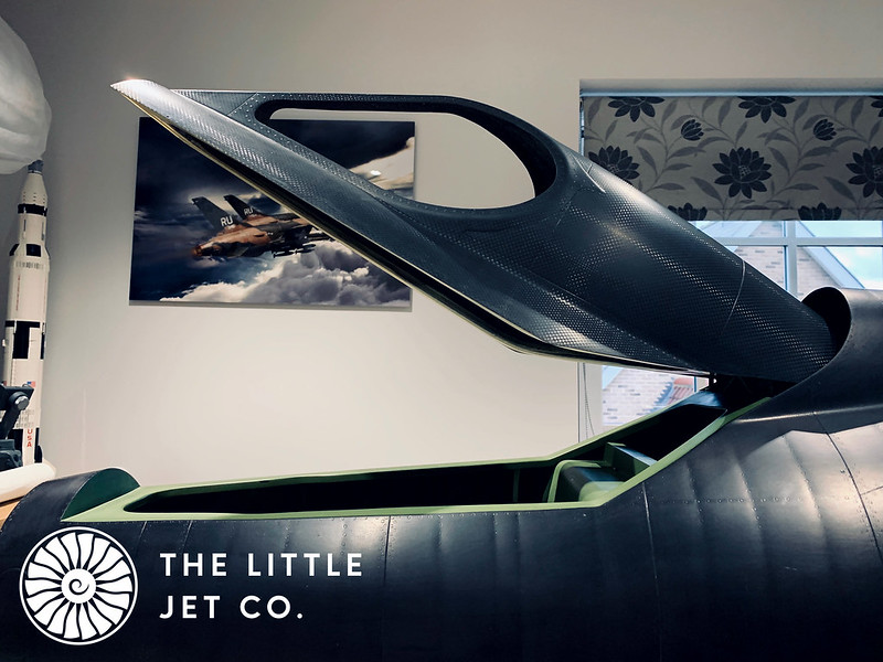
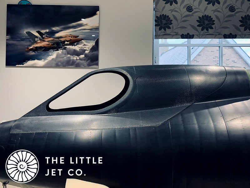
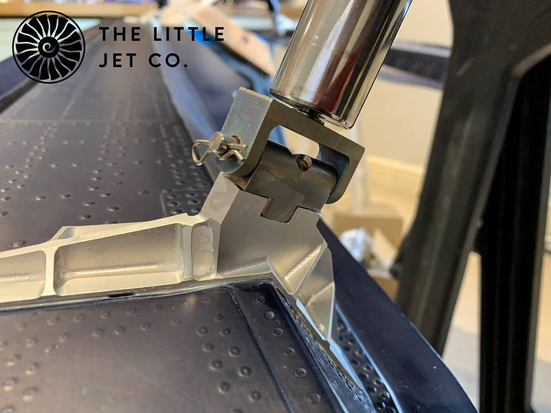
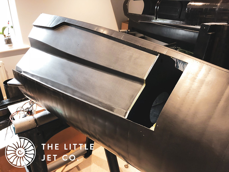
The final aperture cut to size.

IMG_0136
by Alex Jones, on Flickr
 
Last edited:
#2
The job of installing the rear main former was a carful affair as it's essential this is positioned correctly. The forward fuselage former has a recess for a rubber seal. The two halves are fixed in position with large tridair anti vibration fittings allowing easy disassembly of the model for storage or transport.

IMG_2088
by Alex Jones, on Flickr

The forward ski retraction unit is mounted on a CNC'd aluminium former. This needs to be aligned exactly or the ski retraction system when tied to the aft mechanism will not work. Lots of dry fitting and jig building before any bonding takes place! The below photo shows the forward fuselage formers dry fitted with the forward ski wells in place.

IMG_0133
by Alex Jones, on Flickr
 
Last edited:
#3
The formers in the cockpit area are dry fitted at the same time. All the components are tied together through either the Keel beam or aligned with carbon tubes so they need to all be fitted at once. Some trimming was required mainly at the base due to the composite being slightly thicker than specified in this area. I also had a new keel beam cut due to accommodate the increase in thickness. Once this was done the parts slotted in well.

The large painted former you see is a 4mm thick carbon pre-preg component that creates the wet area for the forward ski retraction mechanism. I had made the wet side of this the 'A' side meaning the the moulded edge which is smooth is visible when looking into the ski well. This leaves the 'B' side which is rough and can be seen in the below picture. This needs to mimic a Stainless Steel former so I filled then cut back the B face until smooth.

IMG_0134
by Alex Jones, on Flickr

IMG_0135
by Alex Jones, on Flickr
 
#4
Originally the front ski mechanism could not be removed which was a design oversight on my part so few modifications were required...

I added the two holes you can see so the main front ski pivots can be removed. It's essential that the mechanism can be removed especially during the build as you end up taking it in and out all the time. The white on the the end of the pivots is paint which allowed me to mark the inside of the former so I could cut the holes in the correct place. We also modified the bottom pivot component so it could be easily removed from the inside of the fuselage.

FlickR is down at the moment so I'll add some more pictures later.
 
Last edited:
#5
With all the parts dry fitted and fettled where required it was time to bond everything in place. As everything is interconnected it wasn't really possible to do this in stages, a few of the minor formers where left out as these could be installed afterwards but everything else had to be done in one go, so full commitment with the Hysol 9462!

A nervous 24 hours passed but thankfully all went to plan, although, I won't know if the forward ski mechansim is exactly aligned until we get the skis going up and down. The ski mechanisms have caused plenty of sleepless nights and is by far the biggest challenge as we are operating them exactly like the original aircraft....anyway I digress, back to the forward fuselage. The formers bonded in place.

IMG_0138
by Alex Jones, on Flickr

The cockpit area will have three cameras installed for in flight video so there is nowhere to hide with regard to detail so I have bonded on 0.2mm plasticard over areas which will be visible to the cameras as a base for further detail.

IMG_0147
by Alex Jones, on Flickr
 
#6
The forward ski mechanism had to be in place during the bonding process to ensure alignment. This mechanism was put in the deployed position on a sheet of toughened glass and the fuselage was jigged level while resting on the forward mechanism. The mechanism itself is made up of Titanium, Stainless Steel and Aluminium. A picture of the finished parts assembled for the first time.

TLJC FWD SKI MECH View 2
by Alex Jones, on Flickr
 
Last edited:
#7
It seemed a shame to paint parts but they were sent up to FighterAces for painting regardless. Once back I removed any paint that had found its way into the pivots and re-assembled ready to fit on the former. The actuator is a custom length Bimba product which puts out around 250lbs of force on the upstroke. You would want to get your fingers trapped in during a cycle!

The mechanism is mounted on a removable circular plate which bolts onto the main former and seals with a large O-Ring.

IMG_2196
by Alex Jones, on Flickr

IMG_2197
by Alex Jones, on Flickr

IMG_2198
by Alex Jones, on Flickr

This shows the position required before bonding, the right hand carbon ski well hasn't been installed at this stage.

IMG_2202
by Alex Jones, on Flickr
 
#9
I forget to mention that the colours in the photos aren't accurate but I'm sure you all know the colour we've gone for.

Onto the canopy ... This has been a major pain! Mainly because of the a design oversight in that the canopy is the exactly the same size at the fuselage, maybe even slightly larger due to making a carbon pre-preg part in a glass tool. We couldn't make pre-preg tooling as the pressure in the clave would have destroyed our wooden pattern so it's a limitation of our process more than anything. Ideally you would always want the tooling to made from the same material as the component. In our future projects the tooling will be done a little differently so we can get better quality tooling although for a one off project what we have is adequate.

The canopy needs to rotate down into the fuselage so lots of carful trimming was required! I got it to stage that I was happy to bond the hinge formers in with canopy which is what you see here.

IMG_0051
by Alex Jones, on Flickr
 
#10
The canopy was originally moulded with a return but as the canopy was slightly oversized I decided to completely remove this. I could then trim the canopy with ease. I trimmed it to sit slightly lower than the fuselage at the rear to allow the backward rotation. With the fuselage being constructed from Pre-Preg this allowed me to trim the rear of the aperture to a fine edge allowing the rearward rotation of the canopy without compromising the strength of the trimmed edge. I replaced the canopy return with glass sheet bonded in place with Hysol.

IMG_0144
by Alex Jones, on Flickr

This shows the rearward rotation of the canopy and the edge of the aperture which is around 0.3mm in the area where the canopy needs to miss. It's only a small segment because the rotation immediately presents a smaller part of the canopy to the aperture.

IMG_0139
by Alex Jones, on Flickr

The hinge structure in the rear of the canopy.

IMG_0143
by Alex Jones, on Flickr

This is a large canopy and to show some mechanical sympathy to the servo that will operate it we have to counter balance. To do this was pure trial and error. I ordered lots of springs and fitted each until I found the perfect balance. It now takes very little effort to move the canopy in any position.

The springs temporally fixed in place.

IMG_0146
by Alex Jones, on Flickr

After a lot of work we finally have a working canopy that doesn't bind and is counterbalanced nicely. Now I have to work out how to seal it! We're thinking along the lines of an inflatable seal? More thought required...

IMG_0148
by Alex Jones, on Flickr

IMG_0150
by Alex Jones, on Flickr
 
#12
While stuck back at the computer doing some design work I thought I'd make use of nice winters Monday to test the engines. After the problems with one of the engines (more accurately the fuel pump) in the last test I swapped the engine, pump and ECU for one of our spares. I found as the pumps have been sitting around for a long time they needed around 20 liters of fuel put through them at 6v to loosen them. With this done the engines started nicely... I could have upped the initial voltage during start to the pump but if I had done that eventually I would have had a wet start so better to start with not enough fuel rather than too much during the initial ramp up. I also discovered a fuel leak around the output nipple of the pump on engine No2. I'll replace the tubing and wire lock this in place and hopefully that will solve the problem. It has certainly been beneficial using a test stand as if all this was installed into the aircraft it would have been a massive PITA to sort out.

With both turbines running I could only get to 75% thrust before the rear of the stand started to lift. The stand was pegged and tethered but I still didn't want to risk the full thrust of both. The model will certainly have a tendency to pitch down with an increase in thrust. The initial water based testing will be interesting!

A very short video...

 
#13
With the forward fuselage structurally complete I can move onto the rear. The purpose is to install only what is required initially to allow the ski retraction to actuate. We still don’t know how successful the ski retraction will be and with this part of the project taking a high proportion of the entire design and manufacture time I’m nervous that it won’t work…. Very nervous…

The first task was to dry fit all the formers and do the inevitable fettling to get them all to fit snugly in place. I’m primarily concerned with the first two formers in the aft section. These were fitted with the carbon ski wells in place. In conjunction with the keel beam slots, moulded return of the ski wells and formers including the main pivot block it all essentially self jigs into place. I bonded the first former and ski wells into place but left the main pivot block and second former which takes the load from the skis as I’m unsure if this part will require a re-design if the skis don’t retract.

IMG_0141
by Alex Jones, on Flickr

I’m now at a stage where I can fit the prototype parts of the ski mechanisms and see if the skis will push up into place by hand. It’s a different matter to actuate it prototypically but at least I can see if the mechanism folds away as designed and the ski seats correctly on the side of the fuselage.

IMG_0213
by Alex Jones, on Flickr

Did I mention earlyier I was nervous? This is where all my years of being around aircraft, models, engineering, all my academic and practical experience in aerospace for the last 30 years was bundled together and dropped kicked out of my brain… :(

In my excitement on receiving the machined aluminium pivot block and stainless steel pivot pins I immediately installed them without any lubrication, without even checking the machined parts or removing any burrs and not installing the PTFE bushings (these were the raw machined parts with no finish post applied) After about three turns the whole thing seized inside the pivot block. The next three days were spent trying to remove the pivot block without damaging the composite fuselage or stainless steel pivot pin. After much head banging and profanity the only option left to me was to cut the block out with an angle grinder sacrificing the machined parts in order to save the fuselage. I had to remove a 2 inch square section from the carbon ski well to allow the external part of the pivot arm to fit through the ski well. I then set about destroying the pivot block taking care not to damage any of the hull composite.

It would have been unfair and just not right on my client to have charged for any of this time or replacement parts so I was rather grumpy with myself to say the least at having lost an entire week due to not engaging my brain! I did, however, manage to remove the block without compromising the composite hull.

IMG_0216
by Alex Jones, on Flickr

Another week past and the new replacement components arrived. These were then inspected, polished to the specified RA, bushings and O-rings installed, greased and finally installed into the pivot block. This of course is what I should have done the first time...Let us never mention this again!

I can now see if the ski would at least push into place. The below video shows my initial thoughts.


Yay… although actuating it on what is a very short moment is still making me nervous, less so than before though…
 
#14
Onto assembling the oleos... This was a relatively simple affair. I cleaned up the machined components and polished all the surfaces to the specified finish which should help the stanchion move freely in the oleo. The seals were installed and the entire assembly greased. They were tested overnight with no pressure loss seen.

IMG_0266
by Alex Jones, on Flickr

IMG_0267
by Alex Jones, on Flickr

IMG_0342
by Alex Jones, on Flickr

IMG_1112
by Alex Jones, on Flickr

IMG_0263
by Alex Jones, on Flickr
 
#15
With the oleos assembled and installed we could move on with getting a better understanding of how our ski retraction system works. The first task was to add pressure to the rear actuation while moving the front of the ski by hand. We’re using relatively high pressures (for a model) with large pneumatic rams some capable of large linear forces that would happily crush your hand. With this in mind we started off just adding a little pressure with a hand pump to the extension stroke of the ram.

We designed the gear to retract on ram extension as you get the most force from the ram on this stroke and we knew that we needed all we could get due the short moment involved. Initially I had chosen a set of large Bimba actuators for the rear retraction but on reflection this was the wrong choice as they were very industrial and on the heavy side. I had squeezed the largest actuators possible into the space available and really it was too tight for these. I changed the design to accommodate two Festo DNSU-25-60-PPV-A actuators. These have a bore of 25mm and a force of 29kg on the extension stroke at 6 bar (87psi). These actuators are light, well made and being off the shelf readily avialable.

Our first attempt captured on the phone.


The main pivot block is only dry fitted but as you can see in the above video the ski retracts but not in the correct position. It seats too high in the ski well hitting the top edge of the well aperture. This isn’t entirely unexpected… Ourselves and the engineers we worked with on the ski mechanisms could never get it to function in CAD as we would have liked. We built in ways of moving the geometry to try and achieve a scale retraction. The twist in the ski you saw was one of these variables moving to help the retraction. This is not scale but does help us get closer to the desired actuation.

We are able to move the geometry of the two most crucial elements in the system. The first is the position of the main slider bar as seen in the below picture. Once the ideal position is found I’ll have a carbon part made which will plug all the gaps and make this section watertight.

IMG_0305
by Alex Jones, on Flickr

The other variable geometry change we can make is the rear ski attachment point. This is a crucial angle which effects how the ski retracts and how it sits in the ski well.

IMG_0303
by Alex Jones, on Flickr
 
#16
With the ski in the correct position when retracted it binds on extension and just won't move if we have it extended and try to retract it. There is a balance somewhere in the geometry that will make it work but we now have to make small steps from the extended to retracted position to try and hone in on the correct balance of geometry's.

Incidentally through our research we don't believe the original worked that well to begin with. The two video clips we have show a rather staggered affair. Also the two clips show different sequence of retraction. Reading between the lines in some of the test pilot notes indicates that perhaps this was the case.

You can see the skis retract on this footage from critical past.

 
#17
After much fettling with angles and changing the offset claw on the main oleo to be central we got a ski that retracts into the ski well. I’d say we were about halfway there as it is still a very modular retraction. The sequence works slightly better with a different actuation order of the front and rear rams but I didn’t film this.

I’m happy so far in that it all seems to be going in the right direction but I do have some redesign work as there are clearly a few issues which I’ll detail in the next posts. Nothing insurmountable but I’m confident I can get a really smooth scale retraction with a little more work.

 
#18
Hi Guys,

As I mentioned in my last post several design modifications were required. Starting with the actuators, these had been checked in CAD and the lengths required were 60mm. In reality this stroke length worked as designed but we never allowed for any slop in the system. The stroke needed to be extended by 5mm so the mechanism could lock. This applied to the rear rams and the forward ram. I also wanted to use a larger diameter ram on the rear actuation as the pressures involved with the 25mm ram currently installed were increasing up to 10bar to get a smooth retraction. We can get a similar level of force at 6bar with a 32mm diameter ram. Changing the rams required a redesign of the mountings. There is a lot of force going through these so we used a 6mm carbon former to mount 4 CNC’d brackets which secure the rams. A ‘U’ shaped 6mm carbon former was installed to transmit the load into the fuselage via the forward spar box. Below shows the new mountings although I still haven’t bonded it all to the side of the fuselage yet.

IMG_0309
by Alex Jones, on Flickr

IMG_0313
by Alex Jones, on Flickr

The actuation for the front has been tweaked and now uses 6mm carbon. The front ram works both skis. If there is a failure we want it to be symmetrical this is particularly important at the front.

IMG_0314
by Alex Jones, on Flickr

This hopefully solves the issues internally, we now need to address the problems in the external mechanism and main pivots.
 
#19
The next issue to address is the unacceptable amount of mechanical play in the mechanisms. If we take each individual pivot point and test it for play we might be forgiven for thinking it seems a good fit. But put those same 17 pivots together and ask them to move at the same time, suddenly it becomes more of a problem as the play on the small moments is amplified significantly. By the time you get to the bottom of the ski the whole thing can move to a level that causes us concern.

The first issue was the PTFE IGUS bearing bushes we had used on every joint. We had a meeting with their rep before committing to these and explained the application etc… All our components were designed at the correct tolerance, however, they just had too much play. I was expecting a nice tight fit and was fairly annoyed at the results. The only option left to us was to design our own bearing bushes. For this we used Phosphor Bronze PB102 and set about designing every bush in the mechanism. Using a set of callipers on our machined components we designed the bushes to have H6 and G6 tolerances which are within 9 & 14 microns (0.009.0.014mm) respectively. This will cure the play between all the pivot shafts and their bearings. Overall I think there are about eighty of these phosphor bronze bushings installed in the mechanisms.

Not the most exciting picture I know but you should get the idea.

PB102 Bushings
by Alex Jones, on Flickr
 
#20
The other area of concern was the main pivot on the rear mechanism. This had been designed in two parts consisting of the SS shaft with one o-ring seal groove and a SS clevis. This holds the main arm which connects to the oleo and moves it along the slide bar. The two slide together and lock using a keyway. This keyway had a small amount of play but even this amplified to an unacceptable level by the time it got to the oleo, compounded by the IGUS bush installed into the pivot block. Unfortunately I was unable to get this out without risking damage to the block.

Original pivot and clevis

IMG_0333
by Alex Jones, on Flickr


We re-designed this whole area and included what the original had to support the main pivot externally. We increased the shaft diameter to match that of the IGUS bush and combined both original components into one single machinable component while reducing all the tolerances.

Re-designed pivot and clevis

IMG_0356
by Alex Jones, on Flickr
 
Top